No brush contact in signal transfer
Contactless transmission removes brush wear at that interface. Inspect support bearings, couplings, alignment and fasteners as specified.
 ROTARYTORQUESENSOR.COM / CONTACTLESS MEASUREMENT
Review torque measuring coupling, spline and pulley torque sensor interfaces. Match bores, spline geometry, speed and external loads. Request a quote.
Request engineering review ↗MT-RTR-CPL / 5–2,000 Nm
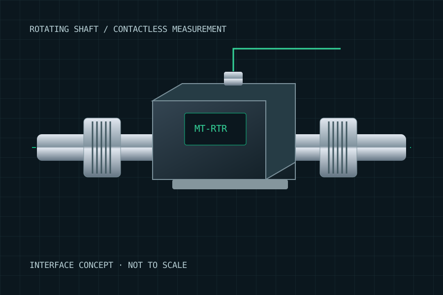
A torque measuring coupling combines contactless measurement with a matched flexible connection. Select the compensation arrangement from the shaft support layout.
Reference review: KTR DATAFLEX · Mayr · HBM coupling-system review. Independent alternatives require mechanical, electrical and calibration acceptance.
MT-RTR-SPL / 20–10,000 Nm
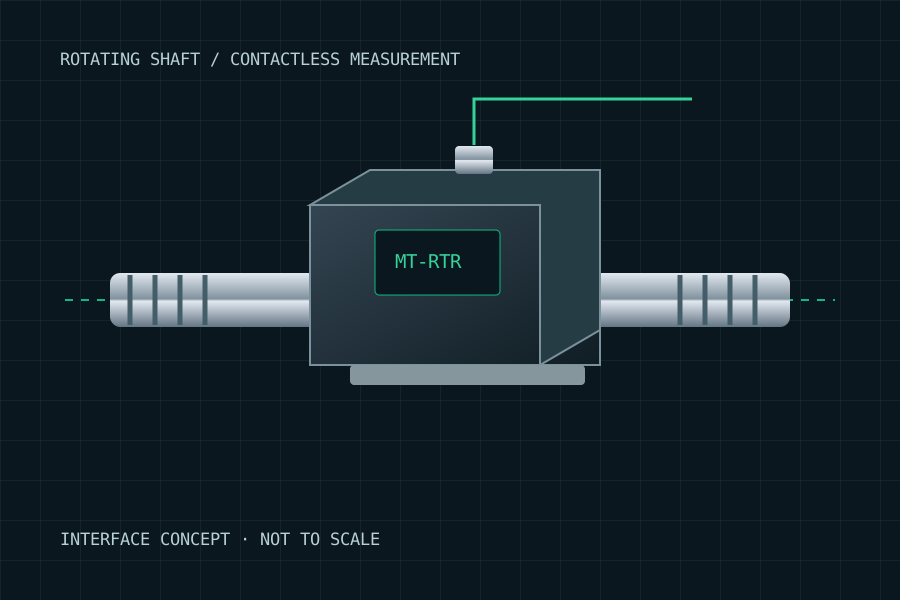
Spline torque sensors and pulley torque sensors for hydraulic drives, gear pumps and belt-driven machinery. Start with the spline definition and external loads.
Reference review: Himmelstein spline references · Interface. Independent alternatives require mechanical, electrical and calibration acceptance.
START WITH THE COMBINED OPERATING ENVELOPE
Series selection targets, subject to configuration approval. Maximum torque and maximum speed are not simultaneous ratings. Request a capacity-specific drawing and calibration specification.
| Model | Rated torque (Nm) | Max speed (RPM) | Shaft diameter (mm / inch) | Built-in output options | Integrated encoder (PPR) |
|---|---|---|---|---|---|
| MT-RTR-CPL | 5–2,000 Nm | Assembly-specific confirmation | Diaphragm or bellows coupling · custom bores | ±10 V / 4–20 mA / RS485Confirm model and pinout | 360 / 1024 requestedConfirm A/B direction support |
| MT-RTR-SPL | 20–10,000 Nm | Assembly-specific confirmation | SAE / DIN spline, hex or pulley · drawing required | ±10 V / 4–20 mA / RS485Confirm model and pinout | 360 / 1024 requestedConfirm A/B direction support |
Configuration targets include 24 V DC supply, active ±5 V / ±10 V / 0–10 V / 4–20 mA torque, TTL speed, RS485 Modbus RTU or CAN. Confirm the actual interface, update rate and pinout on the quoted model.
Requested accuracy options are ±0.1% FS and ±0.05% FS. Ask for separate nonlinearity, hysteresis, repeatability and temperature terms, plus calibration uncertainty. A full-scale error becomes a larger percentage of a small measured torque.
Plan the alignment and coupling arrangement ↗BRUSHLESS / NON-CONTACT SIGNAL TRANSFER
Inductive power and telemetry carry the torque signal across the rotating interface. The shaft rotates continuously; the connector and signal cable remain stationary.
Contactless transmission removes brush wear at that interface. Inspect support bearings, couplings, alignment and fasteners as specified.
Review rotor geometry, capacity, balance and the full shaft train. The bearingless family targets up to 18,000 RPM on selected configurations.
Request active analog or digital outputs for the PLC or DAQ. Confirm 24 V supply, bandwidth, output scaling, cable and protocol compatibility.
| Decision | Contactless telemetry | Brush / slip-ring transfer |
|---|---|---|
| Rotating signal interface | Inductive / telemetry link, no brush contact | Physical sliding contact |
| Wear review | Shaft support and mechanical assembly remain relevant | Include brush/contact inspection for that design |
| Speed & service interval | Use the model-specific specification | Use the model-specific specification |
Modern FUTEK, HBM, Magtrol and Burster models also use non-contact designs. This is a technology explanation, not a claim that those brands use brushes.
YOUR BENCH / YOUR SHAFT DIAMETERS
Send torque and speed together. Include the motor and load shaft sizes for a matched coupling pair.
Request a range-specific drawing, output definition, calibration scope and written quotation.
CAD is supplied for the reviewed configuration. Please send non-confidential requirements first.