
ENGINEERING METHOD / REVIEWED 30 OCTOBER 2026
Begin with the support arrangement, then align the shafts.
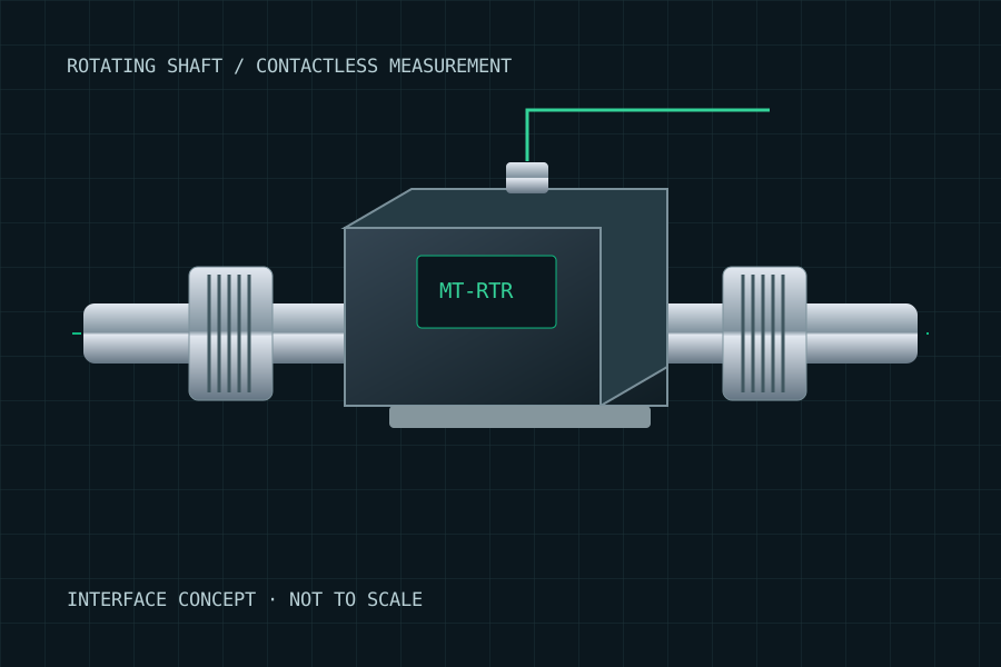
Define the supported shaft train.
Draw motor, sensor, load and every bearing. A bearingless flange has no internal shaft bearings; external supports must locate the rotor. A foot-mounted shaft sensor and a floating arrangement can need different coupling layouts.
Select the flexible elements.
Specify angular, parallel and axial movements separately. Single-flex elements primarily accommodate angular movement; a spaced double-flex arrangement can accommodate parallel offset. Use the actual coupling maker’s limits.
Measure cold alignment and allow for heat.
Use appropriate dial or laser alignment equipment. Check shaft runout, soft foot, center height and axial spacing before final clamping. Do not use flexible couplings to conceal a misaligned machine.
Check the complete speed and load envelope.
Include peak torque, speed ramps, bending/radial loads, critical speeds, hub retention, balance and guards. A pulley’s belt tension is a radial load and may require separate bearings.
Commission torque and speed together.
Verify polarity, zero, encoder scaling and A/B phase where direction is needed. Check filter group delay and synchronized time stamps. Zeroing under an accidental preload can hide a mounting problem.
Check the encoder input rate before ordering.
Pulse frequency f[Hz] = n[RPM] × PPR / 60. At 6000 RPM with 360 PPR, the receiver sees 36 kHz per channel. With 1024 PPR at 12,000 RPM it sees 204.8 kHz per channel. A/B four-edge decoding can produce four times the counts; confirm the receiver’s definition.
Calculate mechanical power with consistent units.
P[kW] = T[Nm] × n[RPM] / 9549.2966, often rounded to 9550. A hypothetical 50 Nm at 6000 RPM gives 31.42 kW. Retain the torque/speed signs and acquisition timing in transient tests. For a pump efficiency calculation, also measure hydraulic power; for a motor, measure electrical input power independently.
Record the acceptance evidence.
Retain mating drawings, approved RPM at the selected capacity, alignment readings, coupling installation instructions, calibration/uncertainty evidence and your low-speed commissioning results.
Request a drawing-led bench review ↗Manufacturer installation references: Magtrol TF installation manual and Burster 8661 operating manual. Their model-specific clearances and ratings cannot be transferred to a different design.