Dual-Range Rotary Torque Sensor for Efficiency Mapping
Compare low and high torque ranges for motor efficiency mapping. Review switching, timing, uncertainty and shaft fit. Send your dual-range configuration request.
Capture low-torque losses and peak load on the same bench.
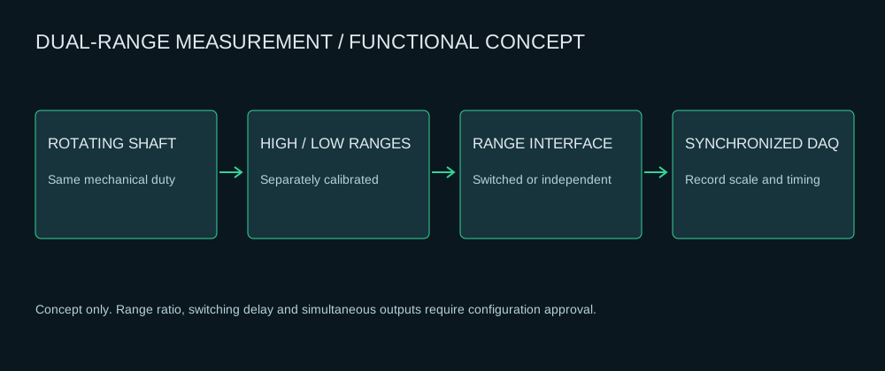
Request separately calibrated high and low torque ranges. Confirm whether the proposed design switches ranges or provides independent simultaneous channels.
Motor efficiency mapping, drag loss and gearbox starting characteristics
Provide peak/continuous torque and the smallest working torque, not only a range ratio.
Verify both full-scale errors, overload protection, switching delay or channel timing.
Confirm the shaft/flange drawing, combined speed envelope and calibration of each range.
Original functional schematic · not a product photograph or released CAD
CAPACITY / SPEED / GEOMETRY / MEASUREMENT CHAIN
Request the complete range-specific data row.
Program envelopes below are planning inputs. An approved drawing must pair the actual capacity with shaft/pilot geometry, maximum RPM, stiffness, inertia and calibration limits.
Program / model status
Requested torque: Nm / in-lb
Dual-range request
RPM planning envelope
Shaft / key / flange interface
Stiffness & rotating inertia
Output / encoder requests
Drawing / STEP / quote
MT-RTR-DRConfiguration program; released SKU pending approval
0.5/5–2,000/20,000 Nm pair requestsEach requested range needs its own in-lb scale
1:5 / 1:10 pair review
15,000 RPM requested
Shaft / bearingless flange · range-pair reviewØ, fits, keys, center height or pilot/BCD from approved drawing
Required with the range-specific drawingNm/rad + kg·m² (or kg·cm², with units)
Analog / frequency / RS485 / RS422 / CAN360 / 1024 / 2000 PPR requests; confirm A/B and receiver rate
1 kg·cm² = 10⁻⁴ kg·m². No stiffness, inertia, shaft diameter or certified speed is inferred from a family name or photograph. Define the calibration evidence.
Specify the signal that your acquisition system needs.
Configuration targets include 24 V DC supply, active ±5 V / ±10 V / 0–10 V / 4–20 mA torque, TTL speed, RS485 Modbus RTU or CAN. Confirm the actual interface, update rate and pinout on the quoted model.
Requested accuracy options are ±0.1% FS and ±0.05% FS. Ask for separate nonlinearity, hysteresis, repeatability and temperature terms, plus calibration uncertainty. A full-scale error becomes a larger percentage of a small measured torque.
Engineering method reviewed . Configuration-specific data are confirmed with your drawing review.
MT-RTR-DR / TWO CALIBRATED SCALES
Separate low-torque uncertainty from peak capacity.
Original functional schematic. Configuration drawings control physical dimensions, support and connections.
One range can hide the loss you need.
Illustrative calculation: ±0.1% FS on a 200 Nm range is ±0.2 Nm from that term alone. At 2 Nm this equals ±10% of reading. The same FS term on a 20 Nm range is ±0.02 Nm, or ±1% of a 2 Nm reading.
These are arithmetic examples, not MT-RTR test results or complete measurement uncertainties. Temperature, hysteresis, mounting, sampling and DAQ effects must also be included.
Two ranges do not always mean two simultaneous outputs.
A switched-range instrument needs range-state and switching-delay handling. Independent simultaneous channels require verified time alignment, cross-talk, channel bandwidth and overload behavior. Specify which arrangement the test needs.
Request 1:5 or 1:10 range pairs, the minimum working torque and the peak duty. Both scales need documented calibration and protection when the low range is exceeded.
Requested pair
Planning purpose
Approval required
5 / 0.5 Nm
Micro-motor drag versus loaded torque
Noise, low-range uncertainty and actual shaft geometry
200 / 20 Nm
Efficiency mapping and starting/continuous duty
Both ranges, RPM, switching or channel synchronization
2000 / 200 Nm
Gearbox or hydraulic drive loss
Peak transients, inertia, combined loading and calibration
Calculate shaft torque or power. Carry the duty into the RFQ.
P[kW] = T[Nm] × n[RPM] / 9549.2966. Mechanical hp uses 745.6999 W/hp; it is not metric PS. Signed inputs follow your shaft convention; capacity uses the magnitude.
The multiplier is your preliminary sizing allowance. It does not establish dynamic overload, fatigue or shaft-train safety limits. Those require the selected sensor and coupling data.
Keep the bedplate constraints. Check every signal separately.
Shafts and mounting
Send both shaft diameters, metric/inch fits, keys, engagement, center height, foot-hole spacing, axial envelope and the original drawing revision. Flange requests also need pilot, bolt circle and fastener definition.
Connector and signal
Send the connector part number and mating-face pin drawing. Compare supply/current, torque scale and polarity, encoder A/B, reference ground, shield and any shunt trigger. A common 12-pin shell does not establish interchangeable wiring.
Approve the complete substitute
Review torque/RPM, inertia, stiffness, parasitic loads, bandwidth and calibration before a mounting trial. Confirm each accepted change in the quotation and drawing.
Customization is assessed from supplied drawings. No universal pin-to-pin or mechanical interchange is promised.
REQUEST THE RECORD, NOT ONLY AN ACCURACY NUMBER
Define calibration and drive-environment evidence.
CW/CCW calibration scope
Request loading/unloading points, zero return, nonlinearity, hysteresis and uncertainty for the sensor/cable/readout combination. Dual-range systems need separate records and scaling for both ranges.
State inverter type, switching conditions, cable length, grounding scheme and required test method. Ask for the applicable report and its exact tested configuration.
No MT-RTR calibration certificate or EMC test report has been supplied for public display. These are document requests; no accreditation or certification badge is implied.
BRUSHLESS / NON-CONTACT SIGNAL TRANSFER
Remove the brush contact. Keep the measurement discipline.
Inductive power and telemetry carry the torque signal across the rotating interface. The shaft rotates continuously; the connector and signal cable remain stationary.
No brush contact in signal transfer
Contactless transmission removes brush wear at that interface. Inspect support bearings, couplings, alignment and fasteners as specified.
Speed is a configuration rating
Review rotor geometry, capacity, balance and the full shaft train. The bearingless family targets up to 18,000 RPM on selected configurations.
Conditioning near the sensor
Request active analog or digital outputs for the PLC or DAQ. Confirm 24 V supply, bandwidth, output scaling, cable and protocol compatibility.
Decision
Contactless telemetry
Brush / slip-ring transfer
Rotating signal interface
Inductive / telemetry link, no brush contact
Physical sliding contact
Wear review
Shaft support and mechanical assembly remain relevant
Include brush/contact inspection for that design
Speed & service interval
Use the model-specific specification
Use the model-specific specification
Modern FUTEK, HBM, Magtrol and Burster models also use non-contact designs. This is a technology explanation, not a claim that those brands use brushes.
DRAWING / PINOUT / CALIBRATION REVIEW
Send the complete bench requirement.
We review the torque/speed duty, mechanical fit and signal chain before proposing a configuration.
Your reply should identify the candidate sensor, coupling bores, drawing/STEP availability, pinout, calibration scope and itemized quotation.
The email link carries the same entries and package options. Your email application opens a draft; send it there to deliver the request. Please share non-confidential specifications first.
Drawings, measured ratings and report availability are confirmed for the selected configuration. Please state your required delivery date and country.
Optional, for up to eight hours since your last edit. Contact details, company, country, quantity, application and original-model reference are excluded. Product pages apply their own series.
Review & download draft requirement
Save a text brief for internal engineering review before sending. Downloading does not submit the request.
Still to provide before sending: Full name; Work email; Delivery country; Target torque and units; Project quantity; Application and duty; Maximum operating RPM; Both torque ranges.
This file includes your entries. Share only with intended recipients.
RotaryTorqueSensor.com | Engineering requirement brief
DRAFT REQUEST — not submitted
This records requested requirements, not a quotation, released specification or calibration certificate.

Rotary torque sensor engineering request
Full name: [your name]
Work email: [your work email]
Company: [optional]
Delivery country: [country]
Series: MT-RTR-DR
Mechanical interface: Confirm from original drawing
Target torque: [Nm or in-lb]
Maximum operating RPM: [RPM]
Dual-range pair: [if required]
Motor / load shafts: [diameters, fits, keys]
Signal: ±10 V
Encoder PPR: 360
Bundle: Sensor + matched coupling pair
Selected options: Integrated speed encoder: 360 / 1024 PPR (+$65 budget; 2000 PPR quoted separately) | Matched diaphragm / bellows coupling pair, custom bores (+$140 budget) | Dual-range configuration review (+$180 budget)
Original model / drawing: [replacement requests]
Quantity: [quantity]
Application: [duty, peaks, bandwidth, environment, target delivery]
Source page: /dual-range-rotary-torque-sensors/
Please review configuration, approved drawing / STEP availability, wiring, calibration scope and quotation.

ENGINEERING REPLY CHECKLIST
- Confirm the combined torque/speed envelope, peaks and required bandwidth.
- Supply the capacity-specific approved 2D/STEP and mating-shaft review.
- Confirm connector pinout, supply, torque output and encoder/PPR.
- Identify actual calibration scope, uncertainty and report availability.
- Itemize sensor, couplings and accessories; confirm price and delivery.
- Confirm dual-range switching or simultaneous channels when requested.

Reply to [email protected] with the request reference when available.
Share this file only with intended recipients; it contains the entries you supplied.