Pump torque transducers for shaft-power and efficiency tests
Measure the power entering the pump shaft, then compare it with the hydraulic output under your declared test protocol. Specify a rotary torque transducer with the correct shaft interface, speed and receiving electronics.
The application context is prefilled below. Add your actual duty and project details; the quoted drawing and evidence define the accepted configuration.
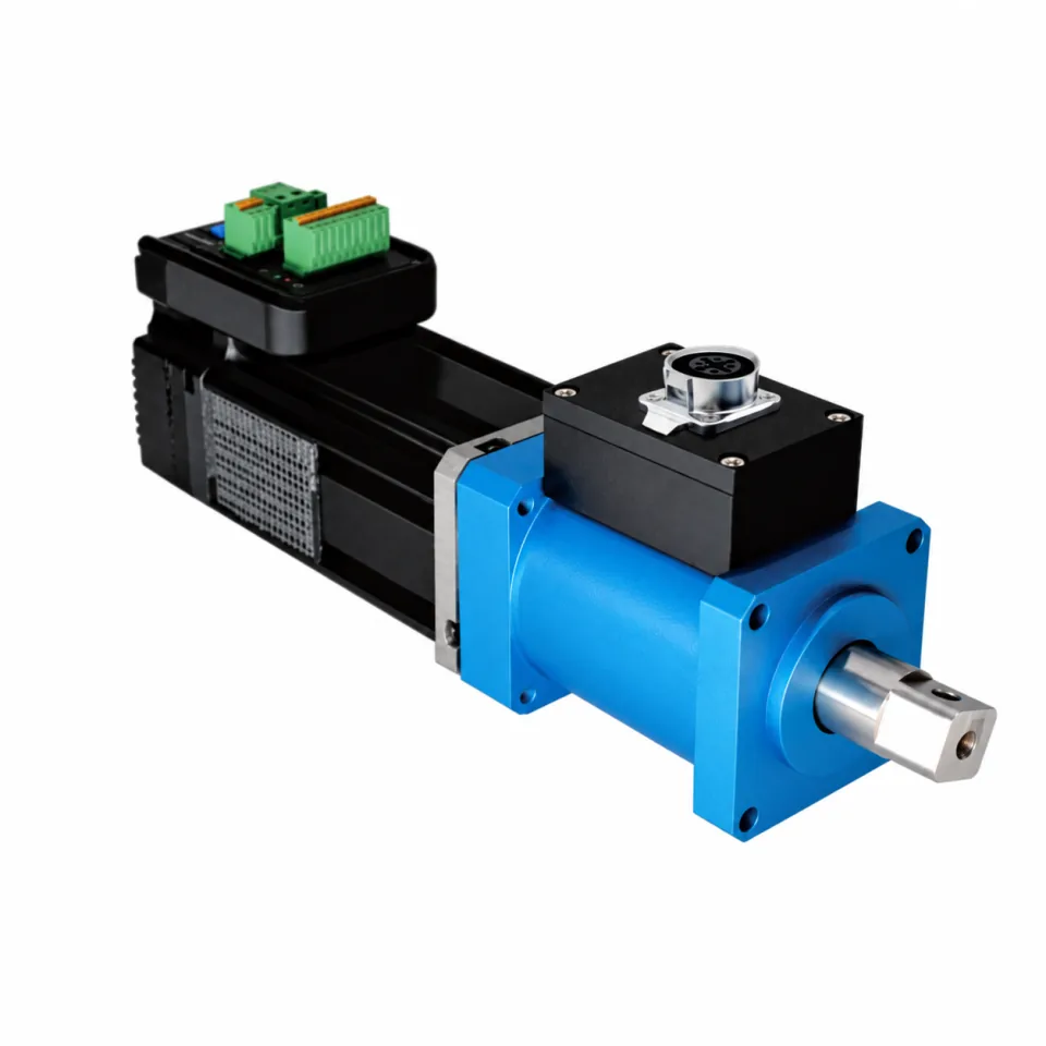
Supplier reference photograph · a family illustration, not a certified application installation.
MEASUREMENT BOUNDARY / CHANNEL ACCEPTANCE
Separate pump-shaft input, hydraulic output and electrical losses.
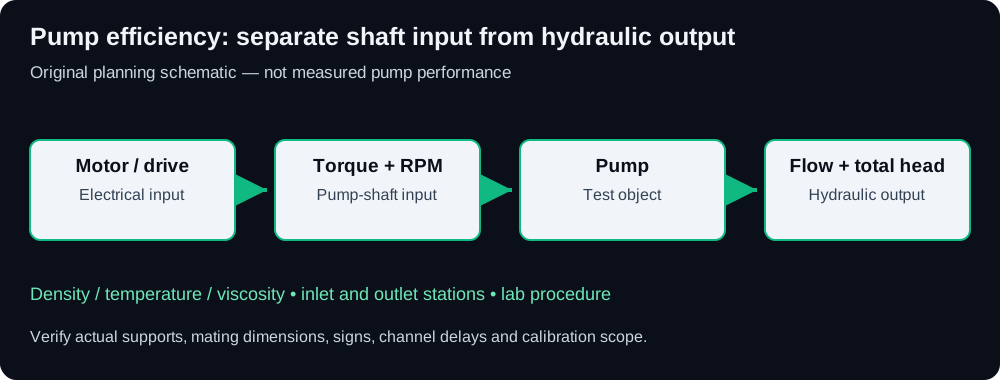
Original planning diagram: electrical supply to motor, measured pump-shaft torque/RPM, and hydraulic inlet/outlet stations. Shaft-to-water efficiency excludes upstream motor/drive losses.
Boundary / channel
Required measurements
Result or calculation
Review before comparison
Pump input shaft
Torque + RPM
Pshaft = T × n / 9549.2966 kW
Define whether seals, support bearings or intermediate drives are inside the boundary.
Hydraulic output
Flow Q + total head H
Phyd = ρ × g × Q × H / 1000 kW in SI
Q is m³/s, density kg/m³ and H is total head in m.
Liquid condition
Density, temperature and viscosity
Reproducible hydraulic duty
Use actual fluid properties and the declared lab protocol.
Electrical input
Measured drive or motor power
A separate overall-efficiency boundary
Do not label shaft efficiency as wire-to-water efficiency.
These are review requirements, not released instrument ratings. Use the actual channel definitions and sign convention agreed for your laboratory.
Choose torque range, connection and signal around the duty.
Direct shaft-to-shaft duty starts with both mating shafts
MT-RTR-605 is a candidate review program for a supported motor-to-pump connection. Supply shaft diameters, keys, fits, axial engagement and maximum torque/RPM together. The sensor does not substitute for the required shaft support.
Spline and pulley drives require their own load path
For a spline, provide the complete geometry and engagement. For a belt drive, identify pulley overhang, belt loads and external bearings before proposing a sensor arrangement. Do not transfer an unsupported radial load into an unreviewed measuring shaft.
The efficiency claim belongs to a defined test system
Declare the pump type, acceptance method, stations, instruments, calibration and operating conditions. Rotodynamic-pump guidance must not silently become a positive-displacement pump protocol. A torque sensor alone does not establish standards compliance.
ORIGINAL HYPOTHETICAL CALCULATION / NOT MEASURED DATA
Calculate shaft-to-water efficiency with total head, not electrical input.
Hypothetical SI point: 20 Nm at 1500 RPM, flow 30 m³/h, total head 30 m and assumed density 1000 kg/m³. Use g = 9.80665 m/s² and Q = 30/3600 m³/s.
3.1416 kWshaft power: 20 × 1500 / 9549.2966
2.4517 kWhydraulic power: ρ × g × Q × H / 1000
78.04%hydraulic output / pump-shaft input
This result is arithmetic, not a pump test or a performance guarantee. Total head includes the relevant pressure, velocity and elevation contributions at the declared stations. A motor/drive electrical measurement would establish a different overall boundary. Obtain the actual liquid properties and apply the lab’s current agreed procedure.
Rotodynamic pump efficiency: measurement decisions before ordering.
Can I compare motor electrical input directly with a pump curve?
A pump curve normally describes pump performance at its specified boundary. Electrical input also contains motor, drive and any intervening losses. Use direct pump-shaft torque/RPM or an explicitly characterized upstream loss model for the chosen comparison.
Can I use pressure rise × flow instead of total head?
Only where the declared method and measurement stations justify that simplification. Different elevations and flow velocities contribute to total head. State the full hydraulic boundary and fluid properties.
Does this worksheet certify an ISO or HI efficiency test?
No. It is a blank planning aid. The lab must define the applicable current procedure, instrument requirements, uncertainty, operating conditions and acceptance criteria.
Method reviewed . The diagrams, examples and worksheets are original planning aids. Actual drawings, range/speed qualification and genuine calibration/EMC reports remain configuration-specific supplier inputs.
APPLICATION-SPECIFIC MEASUREMENT BOUNDARIES
Start with the power boundary your bench must resolve.
EV motor dynamometers
Review peak/low-load ranges and synchronized mechanical/electrical power.
Calculate shaft torque or power. Carry the duty into the RFQ.
P[kW] = T[Nm] × n[RPM] / 9549.2966. Mechanical hp uses 745.6999 W/hp; it is not metric PS. Signed inputs follow your shaft convention; capacity uses the magnitude.
The multiplier is your preliminary sizing allowance. It does not establish dynamic overload, fatigue or shaft-train safety limits. Those require the selected sensor and coupling data.
The email link carries the same entries and package options. Your email application opens a draft; send it there to deliver the request. Please share non-confidential specifications first.
Drawings, measured ratings and report availability are confirmed for the selected configuration. Please state your required delivery date and country.
Optional, for up to eight hours since your last edit. Contact details, company, country, quantity, application and original-model reference are excluded. Product pages apply their own series.
Review & download draft requirement
Save a text brief for internal engineering review before sending. Downloading does not submit the request.
Still to provide before sending: Full name; Work email; Delivery country; Target torque and units; Project quantity; Maximum operating RPM.
This file includes your entries. Share only with intended recipients.
RotaryTorqueSensor.com | Engineering requirement brief
DRAFT REQUEST — not submitted
This records requested requirements, not a quotation, released specification or calibration certificate.

Rotary torque sensor engineering request
Full name: [your name]
Work email: [your work email]
Company: [optional]
Delivery country: [country]
Series: MT-RTR-605
Mechanical interface: Shaft-to-shaft
Target torque: [Nm or in-lb]
Maximum operating RPM: [RPM]
Dual-range pair: [if required]
Motor / load shafts: [diameters, fits, keys]
Signal: ±10 V
Encoder PPR: 360
Bundle: Sensor + matched coupling pair
Selected options: Integrated speed encoder: 360 / 1024 PPR (+$65 budget; 2000 PPR quoted separately) | Matched diaphragm / bellows coupling pair, custom bores (+$140 budget)
Original model / drawing: [replacement requests]
Quantity: [quantity]
Application: Rotodynamic pump efficiency bench: review pump-shaft torque/RPM, hydraulic output boundary, flow/total head, fluid state and synchronized acquisition. Please confirm the application-specific configuration and acceptance documents.
Source page: /pump-efficiency-torque-transducers/
Please review configuration, approved drawing / STEP availability, wiring, calibration scope and quotation.

ENGINEERING REPLY CHECKLIST
- Confirm the combined torque/speed envelope, peaks and required bandwidth.
- Supply the capacity-specific approved 2D/STEP and mating-shaft review.
- Confirm connector pinout, supply, torque output and encoder/PPR.
- Identify actual calibration scope, uncertainty and report availability.
- Itemize sensor, couplings and accessories; confirm price and delivery.
- Confirm dual-range switching or simultaneous channels when requested.

Reply to [email protected] with the request reference when available.
Share this file only with intended recipients; it contains the entries you supplied.